Friday, January 17, 2014

TCS M1 in an older ConCor E8A

The first new installation of 2014 is going to be on a very old model.  In the mid 1980's Con-Cor started to offer a model of the EMD E8A with the mechanism made by Kato.  This model has no flywheels and a more primitive motor that what we have become used to with more current releases.  Many of these models were sold up to the time that Kato introduced their own E8 models in 1994 with a great mechanism that is still in use on current releases of that model.

For this one the frame is going to have to be modified to fit the decoder.  I sent mine to Aztec Manufacturing for precision milling. The Aztec part number is TM3006 and the charge to get this done is only $10.00 plus shipping.  To send the frame to Aztec, fully disassemble the locomotive, put all the small parts in a small plastic and the motor by itself in another small plastic bag for storage until the modified frame comes back.


Decoder wire lengths:


Black  =  4-1/8 inches            Red = 3-3/8 inches             White = 3-3/8 inches              
Blue = 3-1/8 inches               Gray = 2-3/8 inches             Orange = 2-3/8 inches
Yellow = not used

 It's always been my practice to never solder the motor wires from the decoder to the motor brush caps while they were installed on the motor.  Normally with all other installs, I remove the brush, spring, and caps.  Then solder the wires to the caps and then re-install everything into the motor.  On all other loco's I've worked on this works out fine as the caps or brush holders snap into the motor body.  On these ConCor locos the motor brush mount screws into the motor.  With the wires already attached, the wires end up getting very twisted.

This upside down photo shows the correct orientation of the motor and how close the the motor brush caps are to the frame.  The white motor magnet is facing down.

The motor brush contacts point away from the top part of the frame.  When assembled, they made contact with the lower parts of the frame assembly.

So my method for the ConCor cab diesels is this:  I first fully unscrew the mounts and remove them.  Then place a small amount of solder on the surface of the mount.  After it has cooled, I re-install the brush, spring, and the fiber washer and screw the assembly back into the motor with contact part not used.  I don't fully tighten it but leave it loose about 1/2 turn.  Then I solder the tinned motor wire to the spot where the solder is.  The fact that the mount is a little loose, the fiber washer, and the solder already being on the mount seem to keep the mount from getting hot enough to melt the plastic of the motor.  The angle of the wire needs to be pointed upward as shown in the photo below.

When the soldering is done and the brush caps rotated clockwise to a snug fit things should look like this, with the wires pointed upward.


When the motor is re-installed into the milled top part of the frame, the motor wires go up through the slots that are milled.  This view is of the left side of the mechanism with the mechanism upside down.


I have found that the trucks can short on the frame so I add short lengths cut from .010 x .125 strip polystyrene to the areas of the trucks shown in this photo.  The polystyrene strip is held in place with Tap Plastics E6000 adhesive.

With the decoder wires laid out side by side they fit neatly into the milled groove on the top of the frame.  The yellow wire is not used but I keep some length on it in case it needs to be used later.

This photo shows how I connect the decoder input wires to the frame.

On the red wire I used a motor brush contact from a Kato motor to attach the red wire.

On the black wire because the screw is so close to the top part of the frame I did not use any ring.  Instead I just made a loop at the end of the black wire.

To upgrade the lighting to bright white LED first bend the leads so that they will fit around the rasied center part at the end of the top frame.

Place the heat shrink over the wires and solder the resistor to the lead with the smaller element.  Then attach the blue wire to the resistor and the white wires to the lead of the larger element.

This photo shows how the LED assembly fits into the area where the original light bulb was.  It may be necessary to flatten the ridges on the top and bottom of the LED.  The heat shrink will prevent anything from shorting on the frame.  This assembly can be secured with Walther Goo, Tap Plastics E6000 or other similar adhesive.


The model origionally came with black electrical tape over the headlight area to keep the light from shining unrealistically in the cab windows.

I did not see a better way to do it so I did the same thing.  The front edge of the tape should be even with the front edge of  the top frame and the LED.

The shell normally fits rather loosely on the frame so the electrical tape may make the fit more snug on the front end but it should fit.

The fuel tank clips into the shell at two spots on each side and that is what keeps the shell on.


The light should come out brightly on the top large headlight and more dimly on the bottom headlight and the number boards similar to this photo.

Friday, November 1, 2013

Lenz Silver Mini in an Athearn F59PHI

Years ago I had presented an installation for the Athearn F59PHI on my old web site and later included it in this blog as a post.  In that installation I had used the original PC board that was in the engine and the decoder I used was the Digitrax DZ121 which at that time was one of the smallest decoders available.  Here is a link to that post.

Recently I was asked to replace an existing installation of a Digitrax DN121 decoder with a new Lenz Silver Mini.  The PC board had been removed from the locomotive.  So this post will show a different method to install a decoder in this loco that was not available in a DCC version and that no after market decoder board has ever been offered for.

The original installation is seen in this photo.  On this installation, the LED's were not in alignment to get any light into the lenses, particularly the ditch lights that are on this model.

For that reason I felt there would be an advantage to having the LED's and resistors mounted on a board of some type.

This is the Lenz decoder.  Notice how it does not have any heat shrink over it.  That means care must be taken in it's placement so it does not short on any part of the frame.  Also, the wires are more easily broken off from this decoder than those with heat shrink.

My solution to the wire problem is to place a small length of 3/16 inch heat shrink over all the wires near the decoder as shown here.  This acts as a strain relief and will protect the wires being broken off from the decoder during handling.

After removing the motor from the motor saddle and marking at least one of the sides of the motor to keep it's correct orientation, I removed the little tabs that would have held the board in place if there had been one.


A stock board from an Atlas GP40 fits just right into the top of the motor saddle and with some modification it can be used as a replacement board.

I aligned the board so that the front LED is at an equal distance from the front of the frame as on a stock Athearn F59PHI. The black line across the board and saddle mark this alignment.


Notice in the photo above that the little bars on the motor saddle that go across the motor contact wipers on the stock mechanism are gone on the saddle we are using.  This had been removed in the original DN121 installation.  If the loco you are working with is a new installation, this should also be cut.  Too see this step refer again back to the earlier post on this model.

This photo shows the modifications made to an Atlas GP40 board to make it fit into the frame of the Athearn F59PHI.

The polarity of the front LED is reversed so that the anodes of both LED's will be tied together.

I use E6000 adhesive from Tap Plastics to secure the board to the motor saddle and then the decoder to the board.  Because there is no heat shrink on the decoder, it must be placed on a spot where there is no exposed circuitry.

The white, yellow, and blue wires are soldered to the board as shown in this photo and the other wires are trimmed to 2 inches in length.  Keeping them long will make it easier to put things back together.

Route the wires down through the openings in the saddle.  Remove the brush holders from the motor, solder the wires to the brush holders, then after they have cooled, re-install them in the motor. Then connect the red and black wires to the contact strip.  Keep the solder joints small, if needed make the openings in the saddle a little bigger.

On this model the top of the shell is removable so in this photo the installation can be seen after the shell is re-installed on the mechanism.

Several areas to to watch out for are pointed out.

Done !

Saturday, October 5, 2013

TCS Z2 in an Atlas H16-44

The Atlas H16-44 is an unusual model because it has green and red marker lights on each end in addition to a LED head light.  The green markers come on at the leading end of the engine along with the headlight.  The red marker lights are lighted come on at the trailing end.

At the time they were available for sale they came in a DC or DCC version. None of the decoder manufacturers ever came up with an after market decoder for this one so if you want to add DCC to one it's going to be a wired decoder.  I chose the small and reliable TCS Z2 with functions rated at 60ma driving 3 LED's should be no problem.

After some experimenting, I determined that to get the red and green LED's to light using a DCC decoder, both of the 3 lead LED's on the stock board are going to need to be replaced.  This is because they are a common cathode type which means the center or common lead is connected to the negative side of a power source.   On a decoder's function outputs, using the blue wire as a return, it's the blue wire that is positive relative to the white and yellow wires.  Because the LED cathodes are tied together on the PC board, the headlight LED's will also need to be reversed.


I drew up this schematic to show these connections.

I got my 3mm common anode, 2 color ( red / green ) LED's on line from LED-Switch,  www.led-switch.com.  Their item number was L033RGDCA.  It was only $1.50 for a bag of 10 plus shipping.  They are worth checking out anyway as they have quite a few good items for model railroaders.

I could not determine any difference between the common anode and common cathode types of this LED from looking at it.  The only way seems to be to test it.

The method I use is shown in this photo.  If it lights with the + side of the 9 volt battery connected to the center, then it's common anode.  Don't forget the resistor !


There will also need to be some minor modification to the frame so start by fully disassembling the locomotive, placing all the small parts in a plastic bag.    Always put the motor assembly in a separate small plastic bag so no small metal objects will get into it because they are attracted by the motors magnets.  But before putting the motor away see the step below.

There is little plastic part that fits over the end of the motor shaft inside both flywheels.  I found several of these to be quite loose.  This is intended to engage with the worm gear shaft and if it's loose, the mechanical energy won't be properly transferred to the worm gear.

Check both and use adhesive if needed.  I used the E6000 product that I have mentioned in other posts.


I will use the original light board but will cut a section out in the middle to make room for the decoder.  It will end up being two boards with one being longer than the other.

Three diodes and one capacitor will be removed.  The LED's with 3 leads will to be replaced with the common anode ones. The LED's with the heat shrink need to be swapped from one end to the other.

One circuit trace needs to be cut.

The modifications required on the original LED light board are all shown in this photo.

This photo shows  what is now two separate boards should look like after the modifications and where the decoder wires are going to connect when we get to that step.

When installing the new common anode LED's it is important to keep the flat edge of the LED facing the same way as the old one was.  On this type of LED, the flat edge indicates the side for red.

On the the frame modification, I have temporarily placed the PC boards into the frame to gauge the spacing.  The decoder will fit into the wide opening in the top of the frame but that opening needs to be made longer as shown in this photo.

After the material is removed from both frame sides they should look like this.  This is the most time consuming part of this installation but it is important to take the time to be careful working with the frame.

To get the decoder ready for this locomotive cut the red and black leads to 1/2 inch, cut all the others to 5/8 inch.  Strip about 1/16 inch from each of the decoder wires and from one end of the blue, white, and yellow scraps.  Then twist the scrap ends together with their matching color wire from the decoder.

This photo shows what the decoder should look like after this step is completed.  Tin the ends of all the wires, this will keep those twisted ends together.

The next step is to connect the motor to the decoder.  I used a combination of two techniques that I have used on other installs.  The orange wire gets soldered to the wrap around contact to the bottom motor brush and 3/64 inch heat shrink placed over it.  The gray wire gets soldered directly to the top motor brush cap. Remove the brush cap first to do the soldering and then re-install it afterwards.

Put the motor back in it's mounting saddle and re-assemble the mechanism. It should now look something like this photo. Check that both the orange and gray wires are not touching the frame. The heat shrink tubing should protect the contact strip and the orange wire from the frame.
Test fit the shorter PC board, it should fit tightly on both sides. If it is loose on either side, remove the board and tap lightly a few times on the top of the frame at the spots indicated by the blue arrows.  Re-check the fit of the board.  Go slowly and repeat as many times as needed until satisfied that the board is making solid contact with the frame.

Connect all of the wires according to the photo shown several steps back.  When connecting the double yellow wires, place a small length of 3/64" heat shrink over it as there are exposed points on the board very close.  Solder all other wires as shown.

This is what the completed mechanism should look like.  The decoder fits into the little pocket on the top of the frame.

Test run in both DCC and DC modes to verify the lights are all working the way they are supposed to and are synchronized with the direction the locomotive moves.

Monday, August 26, 2013

TCS Z2 in a Kato JR 117 series motor car

Well it's been quite awhile since I've posted any new installs.  It's not that I haven't been doing any, it's just that the types of installs I've been doing I had already covered.  But here's something new, how about a Japanese train.

This Kato set is typical of Japanese passenger trains.  It's a double ended train with a control car at each end and the motor is inside one of the middle cars.  So it actually takes 3 decoders to activate the head and tail lights and the motor.  In this post I'll install the decoder for the motor and will address the end cars later.

The plastic interior comes off by carefully prying off the outside tabs on each side on both ends.  Then pry the interior from the frame at the point shown in this photo to release the interior tabs.


I took a look at the decoder offered by Kato for their Japanese prototype trains but could not see how that would work with this model.  That decoder seems to be designed to use with some of the later releases that have a hatch on the bottom to install the decoder.  I settled on the TCS Z2 for this installation.

After getting the car all the way apart I was able to identify 3 possible locations that the Z2 could fit into.

A - There was room within the roof under the raised part but the wires would be very visible inside the windows.

B - There is a large pocket in the frame here but I was afraid of the decoder rubbing on the drive shaft.

C - I took the conservative approach and chose to just place the decoder inside near one of the ends.

To get the motor out, remove one of the trucks by releasing the 4 tabs as shown in this photo.  Then remove the assembly while pulling the drive shaft out from the motor.  The motor can then be removed while pulling it away from the other drive shaft.

The front and a rear ends to this car need to be established so that when we later add decoders to the end cars so the lights will be coordinated with the motion of the motor car.  To do this I referred to the instruction sheet that comes with the set.  These sheets are in Japanese but I have found the drawing shown below to be very helpful. The cars of this train are numbered 1 to 6 with the motor being in car number 3.  These types of trains are bi-directional and when they reach the end of their run, the operator walks to the control cab at the other end so there really is no front or back. For DCC purposes I like to think of car 1 as being the front.  The writing and arrows under the end cars refer to a destination.

Drawings like this one are in the instructions of each Japanese train set I have seen and are very useful in assembling your train in the correct order.


The orange and gray motor wires are cut at 2-1/2 inches.  These motors are identical to the ones in Kato's American prototype locomotives except there are no flywheels.  The brush assemblies are removed from the motor and these wires soldered to the brush caps.  Then the brush assemblies are re-installed in the motor.  The white magnet on the motor faces down.

After the decoder wires are connected to the motor brushes and the motor is re-installed, the plastic interior piece can be placed between the motor wires as shown here.  Then carefully guide the interior into place on the frame while guiding the orange and gray wires to pass through the gaps between.

The red and black wires can then be cut to the length needed to reach the exposed part of the contact strips and soldered there.  Red to the right and black to the left.  The decoder and wires are held in place with a small amount of adhesive.

Here is the completed motor car.  At a low angle the decoder should be barely visible.  To hide it further, the decoder and wires could be painted a color to match the interior.


OK, so that takes care of the motor car.  This train and ones similar to it also have end cars with both head and tail lights in each one.  that will be covered in a future post.

Saturday, March 23, 2013

DZ123 in a Bachmann H16-44

Recently I had an N engine model to install a decoder into that I had not seen before and as I did not see very much on the web about this model I thought it would be a good one to post on.  Here's how it went.

First step was to remove the shell from the frame.  This model used the bumps on the sides of the frame to position the shell plus it has the ledges along the bottom the the frame for the shell to rest on.  I needed to remove one of the couplers first then I was able to pry the frame up out of the shell by the ledge.

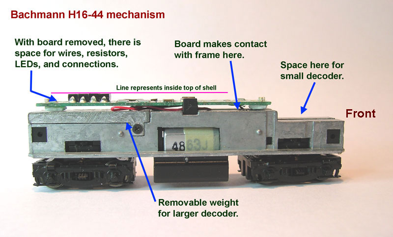
After removing the shell, this is what the mechanism looks like.  There is a board with LED's that is intended to have a wired decoder connected to it.  I was very concerned about the reliability of the connection between the board and the frame.  Also, notice how far the front LED is from the front end of the engine.

Here is a closeup view of the board showing the jumper / connection points that are intended to connect a wired decoder to.  For the reasons stated above I decided not to use this board at all and wire the decoder in directly.

Removing the two screws at the ends of the frames, I opened the mechanism. The way the wires are connected to the motor made me decide to leave them where they are so I cut the motor wires off from the board.  I will be drilling and tapping some holes on the frames so I then removed the motor and the trucks so I have just the frames.


For more detail about how I drill and tap holes in frames to get a secure connection for the decoder input, see the post DZ125 in a Kato F3/7B from January 2011.

Here are the two frame half's after the holes have been drilled and tapped.  Notice how the removable weight toward the rear overlaps both sides.  It seemed so close to being a potential short that I put Kapton tape between the weight and the left frame.


After drilling and tapping the holes, I re-assembled the motor, trucks, and frames before continuing.

With situations like this when I have the motor wires connected I will first check with an ohm meter that both wires are isolated from both sides of the frame and then place the mechanism on the test track and connect the wires as shown to test that the motor is working correctly.

The wire lengths on the decoder are not too critical on this one as there is room to fold over any excess.  I cut the red and black wires to 2 inches and attached motor contact tabs from a Kato install and covered the connection with heat shrink as shown.  The remaining wires will be connected after the decoder is secured on the frame.

Lately I have been using a product call E6000 from Tap Plastics to secure decoders, wires, LED's, etc.  It sets up faster than the Walthers Goo that I had been using for many years.  Here I made a clip from a scrap of brass strip to hold the decoder in place while the E6000 sets.  At this point the red and black wires are secured to the frame with short 2-56 screws.


After the E6000 had set, I spliced the red motor wire to the gray decoder wire and the black motor wire to the orange decoder wire covering each splice with 3/64" heat shrink tubing.  The white and yellow decoder wires are cut to the desired length and connected to T3 size bright white LED's through 1.5K ohm, 1/8 watt resistors.  The blue decoder wire goes first to the front LED and then to the rear LED.

Here is a view of the completed mechanism.  The LED's have also been secured with E6000 taking care to have them aligned toward the headlight lenses.  Any excess wire length is folded over and secured to the top of the frame with Scotch tape.

Finished

This is a view of the short hood or front end of the engine on the layout.  The new LED in its location closer to the end of the frame now gives a bright head light.