Richmond Controls of Richmond, Texas has been providing small lighting modules for model railroaders for many years. Features may include constant brightness head lights, MARS lights, simulated rotary beacon, and other similar features. For more information about Richmond Controls check out their web site.
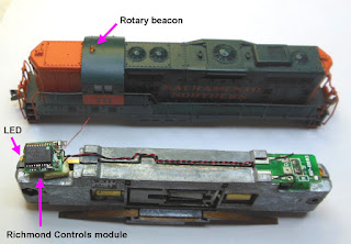
This photo shows the Richmond light module on the left at the short hood end of the frame. It's input is wired to the standard LED board on the long hood end to get contact to the frame.
First I wanted to verify for myself that the Richmond light module current draw was within what the function output of the TCS M1 decoder could provide. The current draw was between 5.5 and 6.1 ma depending on the cycle of the rotary beacon. This is well within the stated 100ma rating for the M1's function outputs.
A variable DC power supply was used for this test and the current draw did not change much between 6 and 12 volts.
To start this installation, the mechanism will need to be fully disassembled.
Normally on a straight forward DCC install on this model, I would have used a TCS CN-GP decoder without frame modification.
In this case to have room for the Richmond module I went back to my old method of using the TCS M1 wired decoder and a frame milled by Aztec Manufacturing.
This particular model is notorious for being noisy. This has been traced to vibration of the inner bushing of the worm gear assemblies. The assembly will support itself between the outer bushing and the flywheel so the inner bushing can be removed. While this is apart for decoder installation is a good time to do this.
I did not invent this technique myself, but read about it years ago in N Scale magazine. Here is a PDF reprint of that article.
To remove the inner bushing, first pull off the hex shaped part from the end of the shaft then remove the bushing and put the hex part back on. The hex part must be a tight fit on the shaft as it is what interfaces with the flywheel. I will normally use adhesive such as E6000 to secure this part to the shaft.
Tip:
If you ever have a locomotive where one or both sets of wheels don't turn when the motor is running, check this or it's equivalent part for being loose on the shaft.The decoder wires are cut to the following lengths:
Black / Red = 2 inch
Orange = 1-1/8 inch
Gray = 1-5/8 inch
The White and Blue wires can be left alone for now.
As with many of my other installs, I file a groove on the side of the motor body for the longer of the motor wires to reach the bottom of the motor
One of the original LED boards is cut off so that there is just enough circuit trace sticking out from the frame to solder the red and black decoder wires to. This is then installed at the short hood end of the mechanism.
The Richmond Controls module is then attached to the frame in remaining space with either double stick or adhesive.
The yellow is cut to a length that will allow it to be folded over the decoder and connected to the cathode side of the T3 size LED.
The blue wire from the decoder is cut a bit shorter than the yellow wire and then spliced with the section of blue wire that was cut off. Both are then connected to a 680 ohm 1/8 watt resistor. The resistor is then connected to the anode side of the LED. Heat shrink tubing is used to cover these connections.
The remaining blue and white wires from the decoder and the red and black wires from the Richmond module can now be cut to a length that they will meet and can be spliced. A 1000 ohm resistor was placed in series to hopefully prevent any over voltage to the Richmond module. Splices are contained within small heat shrink tubing.
When the body is placed back on the mechanism, care must be taken with small wires to the rotary beacon.
Also, it is best to check the coupler height for both ends of the locomotive against a Micro-Train reference. This the body of this model is a loose fit on the frame and if the body is sitting too low it can cause coupler height problems and the bottom of the body hitting the rails. It may be necessary to place shims made from polystyrene strips on the inside of the top of the body.
Recently I've been learning how to work with YouTube a little bit and thought a good way to end this post was with a short video showing the simulated rotary beacon on this model in action.


No comments:
Post a Comment