Prior to programming the routes, I set up the DS64 to control stall motors as I am using Tortoises and to activate all 8 inputs. This is done as Op Switch settings and was well enough explained in the Digitrax documentation that I did not have any trouble getting through it. When I got to programming the routes I found the instructions a bit confusing but eventually figured it out. I wanted to make some good notes for myself and thought this might make a good blog post in case anyone else might need some help on route programming.
First just a bit about the DS64. I had used two of the older DS54's on an old layout and they worked great. The DS64 has all the same functions but is a big improvement in mounting and connections.
This product gives you three choices for power. It can be powered from the track by connecting the track to the terminal strip connections marked "TRKA" and TRKB".
Or a 12 volt DC source with a standard power plug can be connected at the location shown in this photo.
The third power option is the one I am using.
I am running my stationary decoders and some other circuits from a main 12 volt DC power supply which is connected at the two terminals marked with AX1(-) and AX1(+) pointed out in this photo
And now on to the route programming
I am going to use the DS64 that controls one of my staging yards as an example. In this particular project all 4 of the outputs and all 8 of the routes were used to accomplish what I wanted to do.
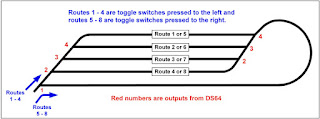
This modified graphic from the control panel shows how the eight possible toggle switch selections relate to the 8 routes. 3 of the outputs will drive 2 turnouts each with the 4th driving just one turnout.
Part of the process of programming routes is to assign addresses to the inputs and outputs, and also a top or pseudo address for the route. Besides being activated by the inputs, the routes can also be activated by calling up their addresses on the throttle. Each individual output can also be accessed by the throttle. It is best to develop a plan and to write out all the addresses that are to be used.
The easiest way to program most DCC devices is to interface the Loconet to a computer and use Decoder Pro software. Unfortunately Decoder Pro does not yet have any provision to program routes on a DS64. The route programming is done with the DS64 connected to an active Digitrax command station by a Loconet cable. The routes are programmed one at a time using the button on the DS64 and a throttle. If a mistake is made on one, it won't effect the others.
Referring to the table above, I have given the routes 1 to 8 on this decoder top addresses of 21 to 28 which can also be used to activate the routes from a throttle. The outputs on this decoder are addressed 11 to 14. This all happens as the routes are programmed.
This next table shows the details of all the steps to program that first route.
This process is repeated for routes 2 to 8 with the only differences being the "C" and "T" settings. Hope you have found this helpful. Once properly programmed the DS64 has proven very reliable for me.


