Saturday, July 2, 2016

Programming routes on a Digtrax DS64

Stationary decoders can used to control turnouts and other accessories on a layout. One of the most popular ones is the Digitrax DS64.  On my current home layout I have two DS64's in use.  One of these controls a double ended staging yard and the other a pair of cross overs.  I have programmed each of these to use the inputs connected to panel push buttons to select the routes.

Prior to programming the routes, I set up the DS64 to control stall motors as I am using Tortoises and to activate all 8 inputs.  This is done as Op Switch settings and was well enough explained in the Digitrax documentation that I did not have any trouble getting through it.  When I got to programming the routes I found the instructions a bit confusing but eventually figured it out.   I wanted to make some good notes for myself and thought this might make a good blog post in case anyone else might need some help on route programming.

First just a bit about the DS64.   I had used two of the older DS54's on an old layout and they worked great.  The DS64 has all the same functions but is a big improvement in mounting and connections.

This product gives you three choices for power.  It can be powered from the track by connecting the track to the terminal strip connections marked "TRKA" and TRKB".

Or a 12 volt DC source with a standard power plug can be connected at the location shown in this photo.


The third power option is the one I am using.

I am running my stationary decoders and some other circuits from a main 12 volt DC power supply which is connected at the two terminals marked with AX1(-) and AX1(+) pointed out in this photo


And now on to the route programming

I am going to use the DS64 that controls one of my staging yards as an example.    In this particular project all 4 of the outputs and all 8 of the routes were used to accomplish what I wanted to do.

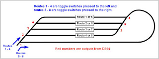
This is the control panel for the yard.  The yard is a reverse loop with 3 sidings on one side. There are 7 turnouts including the one forming the reverse loop.  4 momentary center off double pole toggle switches allow for selection of 8 different routes.

This modified graphic from the control panel shows how the eight possible toggle switch selections relate to the 8 routes.  3 of the outputs will drive 2 turnouts each with the 4th driving just one turnout.


Part of the process of programming routes is to assign addresses to the inputs and outputs, and also a top or pseudo address for the route.  Besides being activated by the inputs, the routes can also be activated by calling up their addresses on the throttle.  Each individual output can also be accessed by the throttle.  It is best to develop a plan and to write out all the addresses that are to be used.

This table represents the addresses I have assigned to the routes and the outputs.  I used this as a guide when doing the route programming reading this across from left to right for each route.


The easiest way to program most DCC devices is to interface the Loconet to a computer and use Decoder Pro software.  Unfortunately Decoder Pro does not yet have any provision to program routes on a DS64.  The route programming is done with the DS64 connected to an active Digitrax command station by a Loconet cable.  The routes are programmed one at a time using the button on the DS64 and a throttle.  If a mistake is made on one, it won't effect the others.

Referring to the table above, I have given the routes 1 to 8 on this decoder top addresses of 21 to 28 which can also be used to activate the routes from a throttle.   The outputs on this decoder are addressed 11 to 14.  This all happens as the routes are programmed.

This next table shows the details of all the steps to program that first route.


This process is repeated for routes 2 to 8 with the only differences being the "C" and "T" settings.  Hope you have found this helpful.  Once properly programmed the DS64 has proven very reliable for me.

Sunday, May 15, 2016

Test fixture for TCS CN type decoders

For wired decoders I used always used a test fixture of some sort in case I wanted to test it before installation or in case I had issues with it and wanted to test it separately.   In the February 2011 post Building a decoder tester I showed how I built the one I am currently using.

Of course now there are many decoder models that have no wires.  I wanted to come with with some sort of easy connections to my decoder tester to accommodate those.  The first one I have done is for the TCS CN and CN-GP decoders as I use a lot of those.

I drilled and tapped 2-56 holes on each half of an Atlas GP7 frame half to secure 22 gauge wires.  Then mounted this to a small 1/2 inch thick piece of plywood for stability.  Space for the fuel tank part of the frame was routed out of the plywood and 1/4 inch thick plywood rails on each side hold the frame in place.

The 22 gauge wires from the frame and motor wires from the decoder are connected to the decoder tester.  I had included banana jacks on the decoder tester with this purpose in mind but find that the wire binding post work just fine.

This setup should also work on with the TCS MT1500 decoder.

Saturday, April 9, 2016

TCS M1 in a Kato SD40

This is another one of those installations where I am using a standard wired decoder on a model that was designed to take a specific board type decoder.  In this case the model is the Kato SD40 built on a mechanism that can use either the Digitrax DN163K1B or the Train Control Systems K1D4 board type decoders.  Releases of the SD40 and SD45 after 2002 use this mechanism.  It can be impossible to know what you have until the body is removed exposing the mechanism.

Here is a comparison of the two mechanisms.

The upper photo is the older version and requires the frame to be modified to get any decoder into to it.

The mechanism in the lower photo is the later version which accepts a board type decoder.


Sometimes it happens that someone gets the wrong decoder because they are mistaken about which version they have.  While the board decoder can't be used on the older version there is no reason a wired decoder can't be installed in the newer version.

Looking again at the newer version of the mechanism and comparing a TCS M1 wired decoder along side it can be seen that there is space for this or other similar small decoder under the LED on the long hood end.

As with my other installations where wired decoders are connected to existing boards, the board receives some modifications.  The first step is shown in this photo.

A small section of the circuit traces are removed in the seven locations shown in red in this photo to isolate the various functions.

Then the capacitor that is installed across the short hood end is removed.  This was added by Kato after it was realized that when running at high speed on DC the trailing end bright white LEDs would flicker.  Since this is not going to be an issue using the decoder it can be eliminated.


Next an additional resistor needs to be added at the location shown in this photo.  The value on the resistor should be the same as the existing one.  They will have either a number 271 (270 ohms) or 561 (560 ohms) on them.  I got mine from other stock Kato boards I had but this type of surface mount resistor can be purchased from Electronics supply sources.

All of the decoder wire connection locations are also shown in this photo.

Just as with the board decoder installation, Kapton tape is placed across the top of the frame and over the sides to insulate the frame from the contact wings that extend down from the board.

I found it works best to install the board on the chassis first then put the decoder in it's place and cut the wires to length starting with the ones closest to the decoder.

This photo shows how I placed the decoder with the wires facing backward but it could go either way.  The wires can either go between the leads of the LED or around to one side.
This photo shows all the wires connected


When re-installing the shell, it should rest upon the tabs that stick out from the frame as pointed out by the green arrow in this photo.

Friday, January 15, 2016

TCS MT1500 in a Life Like SW8

For quite a few years Life Like had offered N scale models of the EMD SW8, SW9, and SW1200 switch engines in many road names.  These were never decoder friendly, and have always been one of the more challenging models to do an installation on.  In 2011 I posted in the blog about installing a TCS Z2 in a Life Like SW9/1200 and it's been the most popular post.

A few years ago the Life Like line was acquired by Walthers, and it appears that Walther's has discontinued production of this model.  More recently Micro-Trains released a model of the SW1500  which is using a very similar mechanism to the one used on the Life Like models.

Shortly after Micro-Trains released the SW-1500 switcher model, Train Control Systems came out with a decoder for it called the model MT1500.

I wanted to see if  this new decoder would also work on one of my Life Like SW8's that had not yet received a decoder.

The first challenge in this installation is to remove the body from the mechanism without damaging the contacts that are attached to the inside of the body.
To do this I made a set of 4 shims as shown in this photo.  The shims are shown here with a ruler as a size comparison.

The shims are inserted between the frame and body at the points shown in this photo.  Then the frame can be carefully removed from the body.  It helps to first remove the cab section and weight, then the frame can be pushed out from above.

The MT1500 decoder does not come with any wires because the installation in the Micro-Trains SW1500 uses the wires that are already in the locomotive.  Scraps of wire left over from other wired decoders were soldered to the motor contact clips after they were cut down to the sizes shown in this photo.

After re-attaching the motor contact clips to the motor and installing the saddle the assembly should look like this.  The orange wire is laying is a small groove that I had filed in plastic body of the motor.

 After re-assembling the mechanism it should look like this photo.  The wires from the motor will plug into the sockets on the decoder board.  Lay the wires down flat as shown so they won't get pinched when the body in put on the mechanism.

The SW1500 decoder has a tiny LED headlight which operates as function F0 which is great.  It also has the option of connecting another light or LED to some very tiny contacts on the decoder board.

If you are up to trying to solder wires to these then this could be programmed for a rotary beacon or mapped to function F0 in the reverse to add a headlight on the back of the cab.

After getting the body back on the mechanism it's good to check the coupler height on both ends to insure the body is on correctly.  I had no problems with mine.  This was the easiest installation on one of these models I've done.  The MT1500 is a welcomed addition to the TCS line of decoders.