Evaluation
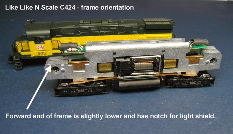
The frame on this model looks almost the same at both ends. The difference is that the front end of the frame is just a little lower than the rear end and has a small notch on each side for the light shield.
With the CN-GP decoder the board that is normally put on the front or short hood end is longer than the other board and I determined that it was not going to fit in that location.
This can be seen in this photo comparing the inside of the shell to the frame with the decoder board.
It was also determined in the same way that the shorter board would fit in this location.
In this photo comparing the rear of the frame with the long board and the rear of the shell with the dynamic brake section removed, it can be seen that the long decoder board will fit if the rear lens is shortened.
I have used this technique of reversing the position of the boards before to fit this type of decoder in the Atlas Classic RS1.
With the dynamic brake section removed and the shell on the frame it was also determined that there would be no clearance for the wires between the top of the frame and the shell so a groove on the top of the frame was going to be needed.
This is really important. If wires are squeezed between the inside of the shell and the frame, the shell may not be seated properly on the frame causing body mounted couplers to be too high. There is also the chance that the wires could become pinched and eventually short on the frame.
Now on to the installation
All of the filing is done on the right half of the frame. There is a small tab that sticks out that I used as a guide. Filing parallel to the length of the frame, I take my time to get a clean notch along the length of the top of the frame. Slots like these take me about 20 to 30 minutes. I don't have measurements but in two of the photos below the results can be seen. The goal is to have enough space for up to 5 decoder wires so that they all lay below the top of the frame.
A slot is also filed with a jewelers file along the side of the motor in the location where the orange wire is in this photo. The orange and gray wires were removed from the decoder and the brush holders are removed from the motor. After the wires are soldered to the brush caps, the orange wire goes to the bottom and the gray wire goes to the top of the motor. There is a hole on the frame of the motor that indicates the bottom.
On the frame and using the motor assembly as a guide, make a notch at the point on the right frame half just above the top motor brush cap. Any edges should be smoothed with a jewelers file.
The decoder boards may be thinner than the stock LED boards. I added a bit of solder to the top side contacts as shown in this photo. Some test fitting and file work may be necessary to get a snug fit on both boards.
At this point, the mechanism is re-assembled and wired.
Here is the completed mechanism in this photo. The motor on this model will rotate a bit within the frame when moved by hand but not by the motor rotating. Once the shell is on, it will hold the motor in place.
Track testing at this point should have the loco running in normal direction in DC and reverse direction in DCC.
Before installing the shell back on the frame, the rear lens needs to be shortened. I removed the dynamic brake section to access the lens. I cut it with a plastic spue cutter then smoothed the end with a flat jewelers file.
In this photo the shell has been installed and the positions of the lens and the LED on the PC board can be seen.
Programming
Because of the reversed position of the boards, CV29 needs to be programmed for 07 if using 2 digit addressing or 27 if using 4 digit addressing.


