Monday, February 21, 2011

A most unusual shorted axle

Yesterday I had received an N scale Precision Craft E8A that I had installed a decoder in about 2 years before that now shorted the DCC system whenever it was put on the track.

The Precision Craft E8 is designed like a scaled down HO engine because it uses wires from the trucks, motor, and LED headlight that all plug into a circuit board.  The board also has an 8 pin connector that either has a decoder or jumper wires if it has no decoder.  I recalled that what I had done was to cut the jumpers on the original plug and then to solder the wires of a DZ125 decoder to the pins.

Here is a stock picture of a decoder like so you can get an idea of what this looks like.


This plug arrangement came in handy when troubleshooting this problem as I did not even have to turn on the soldering iron.  After first verifying that the locomotive indeed did cause a short of the DCC system as soon as it was on the track, I began to unplug things.
  • Unplugged the decoder, still got a short.
  • Unplugged the motor, still got a short.
  • Unplugged the rear truck, still got a short.
  • Unplugged the front truck, still got a short.
At this point, I placed each truck on the track one at a time and discovered that the front truck was the source of the short.  Because all three axles are picking up power and are connected on each side by a metal side frame I took the truck apart to test each axle and find the one that was shorted. 

First I checked the wheel gauge with an NMRA N scale standards gauge and it was OK.  Then pulling the wheels out from each side I could see that the pins that come off the wheels and insert into the plastic tube part were long enough for the ends to touch inside the plastic tube part.  I then took a bit off the end of one of the axle of one of the wheels  with a Dermal tool cutoff wheel and that solved this problem.


Almost all N scale locomotive axle assemblies look like the photo at left.  Two solid metal wheels with metal axle pins that insert into the ends of a plastic tube that has a gear.

It is easy to see how this could happen on any locomotive when the total length of the two metal axle pins are longer than the length of the plastic tube.

I would suspect that this could happen after someone pressed the wheels together to correct the wheel gauge.  The owner of this engine said it started after the engine had derailed.  I suspect that the ends of the 2 axle pins were already very close to touching and getting bumped by the derailment was just enough to make them short.  This ended up being one of those very unusual problems that I though was worth sharing.  I was relieved that the problem had nothing to do with my workmanship and the owner of the locomotive was relieved that the decoder was not burned out.

Sunday, February 6, 2011

Building a decoder tester


I have always found it useful to have a "simulated locomotive" with an actual motor to test decoders.  Back when I started working with DCC, I threw something together from the junk box and ended up using that for many years.

In 2010 that one finally fell apart and I set out to make a nicer one and here it is.


Here's a peek inside.   To keep things simple I mounted all of the components on the top half of the two part plastic project box.  The size of the box is 5-1/2" x 3" x 1-1/2".


The cord that comes out of the box has a Cinch Jones connector on it that I can plug into these two receptacles on my layout control panel.  The layout uses a Digitrax Chief System.

I also have an old Digitrax Big Boy system mounted on a board that I use on the work bench and this decoder tester can also be plugged into that.


Here's a drawing and a parts list along with where I found them.

Besides marking the color for the binding posts, the banana plug sockets are for any special leads needed to connect to board type decoders.


  1. The nickel plated binding posts are Grayhill 29-100 BLK which I purchase from Allied Electronics.  Their part number is 948-7392.  At $4.79 each, this was the most expensive part of the project.
  2. E-Z Hook 9284-5R is a set of banana plug jacks that I found at Fry's Electronics for about $6.00.  The Fry's part number is 18206.  The full set had 10 jacks with colors matching the wires on a decoder.  I did not use the violet or brown ones but if you are working with HO scale decoders that would be something to consider.
  3. Motor assembly from Kato E8 or PA locomotive.  I used this one because the mount was easy to attach to the inside of the box with Walthers Goo.  A striped pattern was printed on adhesive labels and attached to the flywheels to the motors rotation would be easy to view through the windows.
  4. Three yellow LED's taken from Atlas locomotives when they were upgraded to bright white LED's.  One each for the white, yellow, and green (F1).

Wednesday, February 2, 2011

Digitrax DZ123 in a Life Like GP60

This how-to page first appeared on my old web site in December of 2004.

The Life Like GP60 is really a great model but did not come with a provision to install a DCC decoder. To get DCC into this model we will use the Aztec Mfg TM3031 Trackmaster frame and a Digitrax DZ123 decoder. A Train Control System M1 would also work very well in this application. Start by completely disassembling the engine and marking the top of the motor. I always recommend testing a new decoder before cutting any of the wires so do that
now if you have not already. Then cut the wires to the lengths listed below. 
 
2 - 1/8" - Red, Black, & White wires
1 - 3/4" - Gray wire
1 - 1/8" - Orange & Yellow wires

The diagram to the left shows the modifications to the rear PC board and where to connect the yellow wire.

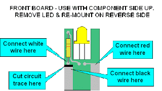
The diagram below shows the modifications to the front PC board and where to connect the red, black, and white wires.

Remove the motor brushes from the motor and solder the orange and gray wires to the motor brush caps.  Next file a groove down the right side of the motor as shown in the photo on the left.  This will be for the gray wire.
This photo shows the front PC board after the engine is re-assembled.
This photo shows the rear PC board after the engine is re-assembled.
To get the gray wire down to the lower part of the motor use a needle file again to notch a groove into the side of the motor housing as shown in the photo. I did this on the right side of the motor but it could be done on either side. Be careful not to get any debris inside the motor.


After the mechanism is re-assembled this is what you will have. The DZ123 is a fit tight. fit.  The TCS M1 is a little narrower and the fit will be easy. The fact that the frame has an undercut that the decoder fits into makes it secure and you will not need any tape to hold it in place. This model has nice locking bumps on the frame like some of the Kato models to align the shell.