Happy New Year and welcome to another year of N Scale DCC decoder installs. During the past year DCC equipped engines have become the majority in my fleet. Maybe this year I can get to 100% DCC !
Starting with the 1997 release of their GP40-2, Atlas started producing N scale engines that could use a board type DCC decoder. The design involved having the bottom motor contact come around to the top and both the top and bottom contacts then touching pads on the bottom of the decoder board or the stock LED board. The idea being that the frame would not need to be modified and this was a great breakthrough for N scale DCC. This same design has been used on many models now and decoder boards to match this design are offered by all the major decoder manufacturers.
This design suffered from that connection between those contacts and the boards not being very reliable. For many years I had been wiring the connection between the motor and decoder. More recently with the wired decoders having gotten much smaller, I have found space between the stock LED boards and the frame and would connect the wired decoder into the LED board. I have posted several of these types of installations here on this blog including the GP40, SD35, and the SD50/60 series.
Recently I had a few U23B's to do but found it was going to be tight to put a wired decoder in the way I have been with those models mentioned above so thought I would give the board decoder another try and have updated my installation as reported here.
The decoders boards for these Atlas engines have evolved over the years and now have plated slots for those motor contact tabs to go through which will help with that connection problem.
Notice in the photo above with the boards that the stock LED board has solder on the frame contact pads. Later we will see why this was done.
This photo shows how far I took the engine apart. The motor and gear assemblies are left in the right side frame throughout this installation.
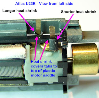
To insure that those motor contract tabs don't touch the frame, I cut two sections of 3/64" heat shrink to cover them. One is 3/16" long and the other is 1/4" long.
After straightening out he motor contact tabs, the sections of heat shrink are pushed down as far as they can go. As shown in this photo the shorter one goes to the top motor contact and the longer one to the bottom motor contact. The tops of the heat shrink sections should be even with the top of the motor saddle. Heat shrinking these is optional. I normally do but suggest being very careful not to use too much heat near the motor.
Remember the solder on the frame contacts of the original LED board ? They did that because the board fit too loosely in the frame. The decoder may also need this treatment. Test fit the decoder board on each side frame to determine if and how much is needed to get a snug fit..
While guiding the motor contact tabs through the slots on the decoder board, press the decoder board into the right side frame as shown in this photo.
Then replace the shoulder washers and press the left side frame on. Carefully guide it on over the decoder board, the shoulder washers, and the motor saddle.
In this close up shot at the right side of the motor after everything is assembled the heat shrink can be seen shielding the motor contact from the frame. The same is true on the other side.
After a successful test run of the engine mechanism, I normally solder the motor contact tabs to the decoder board. Then re-install the shell.
Those tiny surface mount LED's are really bright and make the headlights and number boards look great. Depending on engine paint color, the light may also glow through the shell and a coat of dark color paint on the inside of the shell may be needed. On these dark green Western Pacific locomotives the light did not shine through the shells at all.
The principles of this installation apply to many other Atlas engines using these board type decoders.


No comments:
Post a Comment