Recently I had an N engine model to install a decoder into that I had not seen before and as I did not see very much on the web about this model I thought it would be a good one to post on. Here's how it went.
First step was to remove the shell from the frame. This model used the bumps on the sides of the frame to position the shell plus it has the ledges along the bottom the the frame for the shell to rest on. I needed to remove one of the couplers first then I was able to pry the frame up out of the shell by the ledge.
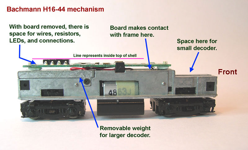
After removing the shell, this is what the mechanism looks like. There is a board with LED's that is intended to have a wired decoder connected to it. I was very concerned about the reliability of the connection between the board and the frame. Also, notice how far the front LED is from the front end of the engine.
Here is a closeup view of the board showing the jumper / connection points that are intended to connect a wired decoder to. For the reasons stated above I decided not to use this board at all and wire the decoder in directly.
Removing the two screws at the ends of the frames, I opened the mechanism. The way the wires are connected to the motor made me decide to leave them where they are so I cut the motor wires off from the board. I will be drilling and tapping some holes on the frames so I then removed the motor and the trucks so I have just the frames.
For more detail about how I drill and tap holes in frames to get a secure connection for the decoder input, see the post
DZ125 in a Kato F3/7B from January 2011.
Here are the two frame half's after the holes have been drilled and tapped. Notice how the removable weight toward the rear overlaps both sides. It seemed so close to being a potential short that I put Kapton tape between the weight and the left frame.
After drilling and tapping the holes, I re-assembled the motor, trucks, and frames before continuing.
With situations like this when I have the motor wires connected I will first check with an ohm meter that both wires are isolated from both sides of the frame and then place the mechanism on the test track and connect the wires as shown to test that the motor is working correctly.
The wire lengths on the decoder are not too critical on this one as there is room to fold over any excess. I cut the red and black wires to 2 inches and attached motor contact tabs from a Kato install and covered the connection with heat shrink as shown. The remaining wires will be connected after the decoder is secured on the frame.
Lately I have been using a product call E6000 from
Tap Plastics to secure decoders, wires, LED's, etc. It sets up faster than the Walthers Goo that I had been using for many years. Here I made a clip from a scrap of brass strip to hold the decoder in place while the E6000 sets. At this point the red and black wires are secured to the frame with short 2-56 screws.
After the E6000 had set, I spliced the red motor wire to the gray decoder wire and the black motor wire to the orange decoder wire covering each splice with 3/64" heat shrink tubing. The white and yellow decoder wires are cut to the desired length and connected to T3 size bright white LED's through 1.5K ohm, 1/8 watt resistors. The blue decoder wire goes first to the front LED and then to the rear LED.
Here is a view of the completed mechanism. The LED's have also been secured with E6000 taking care to have them aligned toward the headlight lenses. Any excess wire length is folded over and secured to the top of the frame with Scotch tape.
Finished
This is a view of the short hood or front end of the engine on the layout. The new LED in its location closer to the end of the frame now gives a bright head light.