

Today's small DCC decoders as well as the design of this popular model make it possible to easily install a wired decoder a less expensive alternate to the board type decoders that are made for these models. No frame modifications are needed.

After dis-assembling the loco mechanism, make the modifications shown in this photo. The hole is on the long hood end of the PC board which has the longer wide area. Wire thickness may be different for each manufacturer of decoder so size hole for the decoder you are using.


Guide all of the decoders wires through the hole from the bottom of the board. Attach the decoder to the bottom of the board with Walthers Goo.
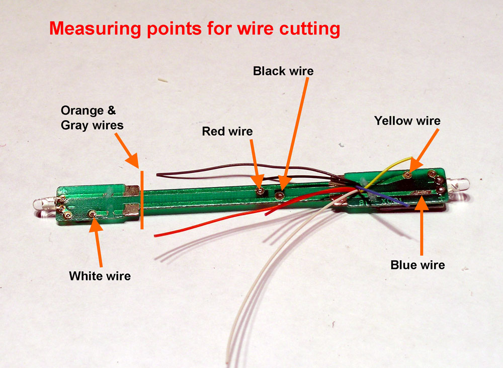
Stretch out each decoder to the point that they will be attached to on the board and cut them about 1/4 inch beyond that. The gray and orange wires will be attached to the motor and I use the line shown on the photo as a length guide for them. This gives a little slack in the wires to work with.
 In this photo the red, black, white, and yellow wires have been soldered to the board. The scrap piece of the blue wire gets used to connect the front LED.
 Study this photo closely.
Trim the motor brush tabs to be even with the top of the motor. Guide the orange wire around the right side of the board and the gray wire around the left side and through the motor saddle.
Place a 1/4" length of 3/64" heat shrink tubing over the end of each wire. Solder the orange wire to the right motor brush tab and the gray wire to the left motor brush tap. Carefully heat the heat shrink tubing then place the motor saddle over the motor from the left side. To make this operation easier is why the length of the orange and gray wires were left as long as they are.

 The original paint on many of these models won't block of light of the bright white LED's and it will glow through. I often paint the inside of the shell around ends with Floquil Old Silver. It also helps to use the same paint around the LED's leaving just the end clear for light to shine through.
No comments:
Post a Comment