Wednesday, February 2, 2011

Digitrax DZ123 in a Life Like GP60

This how-to page first appeared on my old web site in December of 2004.

The Life Like GP60 is really a great model but did not come with a provision to install a DCC decoder. To get DCC into this model we will use the Aztec Mfg TM3031 Trackmaster frame and a Digitrax DZ123 decoder. A Train Control System M1 would also work very well in this application. Start by completely disassembling the engine and marking the top of the motor. I always recommend testing a new decoder before cutting any of the wires so do that
now if you have not already. Then cut the wires to the lengths listed below. 
 
2 - 1/8" - Red, Black, & White wires
1 - 3/4" - Gray wire
1 - 1/8" - Orange & Yellow wires

The diagram to the left shows the modifications to the rear PC board and where to connect the yellow wire.

The diagram below shows the modifications to the front PC board and where to connect the red, black, and white wires.

Remove the motor brushes from the motor and solder the orange and gray wires to the motor brush caps.  Next file a groove down the right side of the motor as shown in the photo on the left.  This will be for the gray wire.
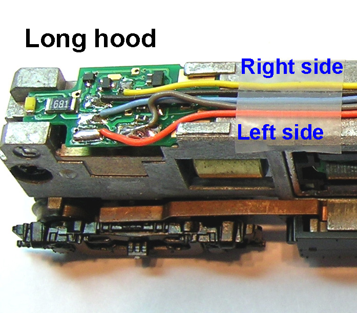
This photo shows the front PC board after the engine is re-assembled.
This photo shows the rear PC board after the engine is re-assembled.
To get the gray wire down to the lower part of the motor use a needle file again to notch a groove into the side of the motor housing as shown in the photo. I did this on the right side of the motor but it could be done on either side. Be careful not to get any debris inside the motor.


After the mechanism is re-assembled this is what you will have. The DZ123 is a fit tight. fit.  The TCS M1 is a little narrower and the fit will be easy. The fact that the frame has an undercut that the decoder fits into makes it secure and you will not need any tape to hold it in place. This model has nice locking bumps on the frame like some of the Kato models to align the shell.

Saturday, January 1, 2011

Digitrax DZ125 in a Kato F3/7B

The original Kato F3/7 mechanism requires frame modification to fit the decoder.  I always send mine to Aztec Manufacturing Co. in Carson City, Nevada.  They do a great job and the price is quite reasonable.  These are on an exchange basis and you will need to send them your original frame.   The Aztec part number for a milled frame for the Kato F3/7 is TM3008.

With the A units, there is a light board that can be used to connect the decoders red and black wires to the frame but what about the B units that don't come with a light board ?  Here is the method that I use.

Start by drilling a hole with a #50 bit just behind the pocket on each half of the frame. Drill to a depth about half way through the frame.  The hole should not hit the hole already in the frame that is for the screw that holds the frame halves together.

I use a small table top drill press that I purchased from Micro Mark.  Because the fuel tank part of the frame would make it hard to hold the frame square, I use a scrap of plywood to support the rear part of the frame.

Then tap each hole with a 2-56 tap.  Kadee part number 246 includes both the drill and the tap.


The motor brush to frame contacts that are in each Kato engine made great electrical mounting rings.  I find them handy for a number of projects and  save all of the I remove when doing installations.
This is the method I use to remove the motor brush to frame contacts on all Kato locomotives. Lay the motor on edge on a flat surface.  Using a flat blade jewelers screw driver, gently pry the brush holder up using the edge of the motor housing as the fulcrum. 
Cut the wires of the decoder to the following lengths:
Red / Blk / Yel / Blu / Wht = 1-9/16"
Gray = 1-5/16"
Orange = 1-7/8"

Solder the removed brush caps to the orange and gray wires, and the removed brush to frame contacts to the red and black wires.

Re-assemble the motor brushes with the decoder wires now attached to the brush caps.

Then place the motor, worm gears, and bushings into the right side of the frame.  Lay the orange motor wire into the slot on the right side of the frame that has milled for this purpose.  Take special care that the motor mounting rings are seated correctly into the frame.  Last install the two black shoulder washers.
Connect the left side of the frame together with the right side again being careful to correctly seat the motor mounting rings.  Then install the nuts and bolts that hold everything together.  Lay the decoder in the pocket that's milled into the top of the frame, attach the red wire ring to the the hole on the right side frame and the black wire ring to the hole on the left side frame with 2-26 flat head screws.  Lay the wires out flat in the milled groove down the middle of the frame and secure with scotch tape as needed.

Saturday, December 25, 2010

Decoder wire cutting guide

Here is a trick I started using years ago to make my installations more quickly and more consistent.

With wired decoders, it's somewhat critical to get the length of the wires cut to just the right length.  Once you know the lengths, you could write them down for future installations in the same type of locomotive.  What I do to save time is to make a card like the one shown in the photo.  Then I just lay the decoder wires out on the card and cut each wire to the length specified on the card with a hobby knife.

It's also a good place to make notes on the card about this particular engine or installation.  For example, on this card I have noted that the white magnet on the motor goes to the top and that this card is referring to the use of an Aztec Trackmaster TM3008 frame and a Digitrax DZ125 decoder. 

Sunday, December 19, 2010

Train Control Systems CN or CN-GP ?

The Train Control Systems CN type decoder is a good choice for some locomotives where they can be installed with little or no modification to the frame.  So what's the difference between the two and where can each be used.  I've been working with these quite a bit lately and have some answers.


The only difference between the two decoders is the shape and size.  The CN is shaped to fit between the parts of the frame that stick up on both ends of the Chinese made Atlas RS and RSD series of locomotives and is slightly longer than the CN-GP.  Refer to the photo above to see a comparison of both types. 

As the name suggest, the CN-GP is designed for the Chinese made Atlas GP series.    Both of these decoders can be used in other locomotives as well, sometimes requiring a little more modification to the frame.  The table below lists all of the locomotive types that I've installed these type of decoders in so far along with brief notes about the installation.  If I have related material in this blog, there will be a link to it.  This table will be updated whenever I discover another locomotive that the CN or CN-GP decoders can be used in.
 
Make and ModelDecoder typeNotes
Atlas GP7 and GP9CN-GP1995-1997 releases - see instructions
Atlas SD7 and SD9CN-GPOld release made by Kato - see instructions
Atlas Classic RS1CN onlyReverse board locations - see instructions
Atlas Classic RS3CN onlySee detailed instructions
Atlas Classic RSD4/5CN onlySee detailed instructions
Kato SD40 or SD45CN or CN-GPRequires slot on top of frame for wires
Kato U30C or C30-7CN or CN-GPRequires slot on top of frame for wires
Life Like C424CN-GPRequires slot on top of frame for wires and reverse board locations, see instructions
Life Like GP60CN-GPMinor frame modification, see instructions


Tuesday, December 14, 2010

TCS CN in an Atlas Classic RS1


For the Atlas Classic RS1 I like to use the TCS CN decoder without removing any weight from the already light frame.  As many of the steps here are the same as with the Atlas Classic RS3, I will only focus on what is different from that installation.

Normally the part of the CN type decoder with the most components goes on the end of the frame that is the forward, or short hood end.  With the Atlas Classic RS1 this would require removal of some material from the frame however the decoder boards will fit perfectly if their positions are reversed.

The photo at left shows a top view of the standard layout to help understand how the decoder defines forward and reverse.  When we swap the position of these boards it's like reversing the red and black wires of a wired decoder.


Follow all of the steps in the RS3 installation except that the main decoder board will be at the long hood end.

Connect the orange and gray motor wires as shown in this photo which will be reversed from what they normally are.

At this point when you test run this engine, it should run backwards on DCC but in the correct direction on DC. 


To correct the DCC direction program the decoder for long hood forward.  This is done by entering 07 at CV 29 for 2 digit addressing or 27 at CV 29 for 4 digit addressing.

This photo shows an overhead view with the decoder boards installed.  After programming CV29 to compensate for the main decoder board being on the long hood end, the engine should run in the correct direction in both DC and DCC modes.

If you are modeling one of the railroads that considered the long hood of the engine to be the forward end, then skip the reversal of the motor leads and the reprogramming of CV29.

Sunday, November 21, 2010

TCS M1 in a Walthers GP38-2

This how to episode first appeared on my old web site in December 2008.

The Walthers GP38-2 did not come with any provision to install a board type decoder but has room for one of todays small wired decoders.  Follow along as I install a Train Control Systems M1 decoder in this one.
As shown in the photo on the left the design of the engine leave space in key areas that we can use.  The existing PC board will be modifiyed and re-used.

Start by fully disassembling the locomotive and make a mark on the top of the motor.
Strip the PC board of all it's parts.  Then make the modifications shown in the photo on the left.  Save teh two resistors from the locations R3 and R4 that are marked "561" and re-install them at locations R1 and R2.
The LEDs that come with the Walthers GP38-2 are standard yellow ones.  I am going to upgrade to sunny bright white LEDs.  I remove the stock LED's from the board and use them as a guide to bend the leads of the new ones to the correct length.
Next prepare the decoder.  Cut the blue wire to a length of 3/4 inch.  Strip about 1/8 inch insulation from the end and from one end of the piece of blue wire that was cut off.  Twist the two stripped wire ends together and tin.
Now solder the two twisted together and tinned blue wires to the spot shown in this photo. Then route all the remaining wire ends through the hole to the top side of the PC board.
Next Solder the black and red wires to the locations shown in this photo. 
Next trim the yellow, blue and white wires to a length to reach the spots shown in this photo.  Strip and tin the ends and solder the wire ends to those locations. 
Cut the orange wire to a length of 1-1/4 inch from where it comes through the hole in the PC board and cut the gray wire to a length of 2 inches.  Strip and tin the ends and solder to the brush caps after they are removed from the motor.


Re-install the brushes, springs, and brush caps in the motor. The gray wire goes to the bottom and the orange wire goes to the top of the motor. Use a small amount of Walthers Goo to secure the gray wire into the groove filed into the motor housing in the previous step. Then wrap Kapton tape all the way around the motor where the brush caps are to insulate them from the frame.   Now reassemble the motor and worm gear assemblies into the right side frame as shown. With this type of mechanism that uses the rings to support the motor great care must be taken to insure that the rings are properly seated into the frame.

With the frame still laying on it's right side, place the washers that separate the frames into the holes and re-install the left frame. Make sure that the mounting rights are seated properly into both frames then re-install the screws and nuts.

Get the front PC board contacts started first, then being careful not to pinch the orange and gray motor wires guide the back of the board down onto the frame. Then push forward to fully seat the boards contacts into the frame.  When the board is fully seated into the frame it should look like the photo above. Lay the motor wires down over the board in the area above the motor. If necessary, secure them with some scotch tape.

Friday, November 19, 2010

TCS CN in an Atlas Classic RS3


This how to page first appeared on my old web site in July of 2008.  The CN type decoders were new then but have grown in popularity as they can be used in many engines.

Refer to the photo on the left.

This type of decoder uses two PC boards which take the place of the stock LED boards.  As the front board does no have a connection to the left half of the frame, both boards are needed for the decoder to work.  I really like the design of these decoders with the tiny but bright LED and large solder pads for the wires that make re-attachment possible.
For this installation I did not have to do anything to the frame.  I started by disassembling the engine and mark the top of the motor.   Lay the front board of the decoder out as shown in the photo on the left and cut the orange and gray wires to the lengths indicated in the photo.

Refer to the photo on the left.

Remove the brush caps from the motor, then remove the contact tabs from the brush caps.  Solder the wires to the brush caps.  File a slot on the left side of the decoder deep enough for a wire to fit but not all the way through the plastic motor housing.  Re-install the brush caps, spring, and brush.  The orange wire should lay in the slot as shown.

Wrap Kapton tape around motor as shown in photo on the left.  Place motor, worm gears, and bushings into the left side of the frame.  Take care to get the motor mounts seated correctly in the frame.

Assemble the frame again taking care to have the motor mounts properly seated.  Check that the flywheels turn freely.  Plug in the decoder boards and trim the black, blue, and yellow wires to a length that will reach the rear board then solder those to the pads indicated in the decoder instructions.

With this engine the way the shell sits on the on the frame leaves just enough space for the wires.  The wires must lay flat on the top of the frame and must not overlap.  Re-install the trucks and fuel tank.

At this point we are ready for a test run.


When satisfied with the test run without the shell, the shell can then be installed.  If the shell is properly seated on the frame, the bottom of the walkways should make full contact with the 4 tabs that stick out on the sides of the frame. 

In the photo on the left the trucks have been removed to make this more visible.


DONE !