Saturday, July 11, 2015

TCS M1 in an Atlas GP7

Yes, this is yet another type of Atlas GP7 installation.   This installation follows an older technique that I don't use much anymore but in this case the model already has a Richmond Controls lighting unit installed and the goal is to continue to use it being controlled by the DCC decoder.

Richmond Controls of Richmond, Texas has been providing small lighting modules for model railroaders for many years.  Features may include constant brightness head lights, MARS lights, simulated rotary beacon, and other similar features.  For more information about Richmond Controls check out their web site.

This photo shows the Richmond light module on the left at the short hood end of the frame.  It's input is wired to the standard LED board on the long hood end to get contact to the frame.

First I wanted to verify for myself that the Richmond light module current draw was within what the function output of the TCS M1 decoder could provide.  The current draw was between 5.5 and 6.1 ma depending on the cycle of the rotary beacon.  This is well within the stated 100ma rating for the M1's function outputs.

A variable DC power supply was used for this test and the current draw did not change much between 6 and 12 volts.


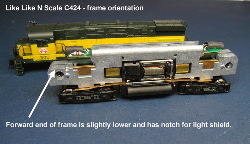
To start this installation, the mechanism will need to be fully disassembled.

Normally on a straight forward DCC install on this model, I would have used a TCS CN-GP decoder without frame modification.

In this case to have room for the Richmond module I went back to my old method of using the TCS M1 wired decoder and a frame milled by Aztec Manufacturing.

This particular model is notorious for being noisy.  This has been traced to vibration of the inner bushing of the worm gear assemblies.  The assembly will support itself between the outer bushing and the flywheel so the inner bushing can be removed.  While this is apart for decoder installation is a good time to do this.

I did not invent this technique myself, but read about it years ago in N Scale magazine.  Here is a PDF reprint of that article.

To remove the inner bushing, first pull off the hex shaped part from the end of the shaft then remove the bushing and put the hex part back on.  The hex part must be a tight fit on the shaft as it is what interfaces with the flywheel.  I will normally use adhesive such as E6000 to secure this part to the shaft.

Tip:

If you ever have a locomotive where one or both sets of wheels don't turn when the motor is running, check this or it's equivalent part for being loose on the shaft.

The decoder wires are cut to the following lengths:

Black / Red = 2 inch
Orange = 1-1/8 inch
Gray = 1-5/8 inch

The White and Blue wires can be left alone for now.

As with many of my other installs, I file a groove on the side of the motor body for the longer of the motor wires to reach the bottom of the motor

One of the original LED boards is cut off so that there is just enough circuit trace sticking out from the frame to solder the red and black decoder wires to.  This is then installed at the short hood end of the mechanism.

The Richmond Controls module is then attached to the frame in remaining space with either double stick or adhesive.

The yellow is cut to a length that will allow it to be folded over the decoder and connected to the cathode side of the T3 size LED.

The blue wire from the decoder is cut a bit shorter than the yellow wire and then spliced with the section of blue wire that was cut off.  Both are then connected to a 680 ohm 1/8 watt resistor.  The resistor is then connected to the anode side of the LED.  Heat shrink tubing is used to cover these connections.

The remaining blue and white wires from the decoder and the red and black wires from the Richmond module can now be cut to a length that they will meet and can be spliced.  A 1000 ohm resistor was placed in series to hopefully prevent any over voltage to the Richmond module.  Splices are contained within small heat shrink tubing.


When the body is placed back on the mechanism, care must be taken with small wires to the rotary beacon.

Also, it is best to check the coupler height for both ends of the locomotive against a Micro-Train reference.  This the body of this model is a loose fit on the frame and if the body is sitting too low it can cause coupler height problems and the bottom of the body hitting the rails.  It may be necessary to place shims made from polystyrene strips on the inside of the top of the body.

Recently I've been learning how to work with YouTube a little bit and thought a good way to end this post was with a short video showing the simulated rotary beacon on this model in action.


Sunday, April 12, 2015

TCS M1 in an Atlas Master Line GP38-2


I recently did an install on one of the more recent releases of an Atlas GP38-2 using the TCS M1 decoder.  While this install is similar to other installs I have presented using a wired decoder instead of a board decoder I discovered some differences that made it worth it's own post.

After dis-assembling the mechanism I discovered that the motor had a different type of brush holder than those found in most Atlas models.  This model uses the Kato style of brush holder with a separate cap.

The plastic motor saddle had also changed.  Because the brush holder with cap sits flatter than the one piece type, the saddle had a block on both top and bottom.  I found it necessary to remove the top block with a file to get a good fit.

The board requires the same type of preparation as the board did on the Atlas Master Line GP7 that I did about a year ago.

For more for details on how prepare and wire the decoder to the board check HERE.

This model comes with the little spring clips on the original LED board.  I've never had much luck with these and the ones on the board fell off so I used the solder method to thicken the board for a good fit into the frame.

After re-assembly the mechanism looks like this photo.  The model I did was actually a GP38-2 but a master line GP38 should be an identical mechanism.  I test ran this model with an earlier release GP38 and the speed of this new motor seem to match the older release perfectly.

Tuesday, February 3, 2015

TCS ASD4 in an Atlas Master Line GP7

About a year ago I presented an installation where I used a TCS M1 decoder on an Atlas Master Line GP7 which is intended to take a board type decoder but does have room for wired decoder using the existing PC board.  To see that post click HERE.  Recently I was asked to install TCS ASD4 board type decoders in several similar models so I thought it would be good to present that type of installation as well so someone could make the comparison.


What happens sometimes with these decoder board type of installations is that the contact tabs from the motor don't line up with the slots on the board.  The photo shows how I check for this, lining up the frame to board contacts first then checking alignment of motor contacts.


It's not hard to fix this problem by hard wiring the motor contact to the board.  I use scraps of orange and gray wire left from wired decoder installations.  It does not matter which color wire is used as long as the wire from the bottom brush goes to the forward slot and the wire from the upper brush goes to the rear slot just as the tabs would if they lined up properly.


Cut the tab from the lower brush short and solder a wire to it, then slide a short length of 3/32" heat shrink tubing over it.

For the top motor brush first remove the brush holder and take the tab off.  Then solder the other wire to it.  When cooled re-install holder with spring and brush into motor body.

After both wires are attached to the motor assembly, slip them through the plastic motor saddle as the saddle is pressed onto the motor.  When that's all done the finished assembly should look like this photo.

Another issue with the board type decoders is that they sometimes fit loosely in the frame.  On this one I fixed they by adding a small amount of solder to the contacts on the bottom side of the board.  On this model I found that a thickness of .030 was about right to get a snug fit.

Press the board into the right half of the frame, it should fit snugly. On these Master Line GP7 and 9 models, there may be a small plastic button.  That goes into the right side frame as shown here.

When everything is all put back together it should look like this.  The wires need to lay in between the frames.

A nice thing about this decoder board is that is has big solder pads to easily connect extra lighting functions.


In some future post I will show some ways to use these additional functions.

Tuesday, January 6, 2015

Kato SD80Mac slow running

At a recent train show one of my buddies from the Ntrak club I belong to asked me to take a look one of his Kato SD80Mac locomotives.  His complaint was that while it did run, it was slower than other identical locomotives.  I verified this on my test layout and it seemed to get worse the more I ran the locomotive. I then took the shell off to test the motor for current flow and this is what I found.

Apologies for this blurry photo.

The kapton tape was coming into contact with a rotating part of the motor as indicated by the arrow on both sides preventing the motor from turning freely.  This put an overload on the decoders motor output.

This photo shows how the installation should look. The kapton tape comes over the side of the frame on each side and stops before reaching the open part of the motor.

This type of installation is common to several Kato models.  They are generally an easy DCC installation but it is a good practice to always check for free rotation of the motor when doing an install.

When I put the decoder on my test fixture, the voltage on the motor output of the decoder was zero when connected to the test motor but was normal with no load. There was no sign of anything burned on the decoder.  A reset was programmed into the decoder but this did not clear the problem.  In this case the decoder needed to be replaced.

Before installing the replacement decoder the current draw of the motor was measured by connecting the motor directly to my bench DC power supply as shown in this photo.  It is rare but I did once see a defective motor cause a decoder to burn out and that became the first post on this blog.

Monday, October 27, 2014

Kato E8A won't program

Not much new decoder installation material to report on lately but recently at a local show one of the guys in the Ntrak club was having trouble programming one of his Kato E8A's that he had just put a decoder in.  On our Digitrax system the throttle display indicated "NoPrG".

This photo shows the decoder installation. A visual inspection indicated that everything was done according to instructions.


What I found when I got this loco to my bench was that the motor contact strips were not making good contact with the board.  This is a common problem and I always solder the contact strips to the board.  What happens is that a current has to pass through the motor to complete programming.  That is why you may notice a loco move or feel a vibration when sending it a program.  On this type of mechanism the motor brush contact strips are held in place against the board by a plastic clip.  This clip by itself sometimes does not stay tightly in place.

This closeup shows how the motor contact strips are held against the board by the clips.  To solder the contacts in place, remove the clip and melt a small amount of solder to both the board and the bottom side of the contact at the end.  Then use a small screwdriver to hold the contact tight against the board while re-melting the solder making the bond. Care needs to be taken to avoid melting the kapton tape on the wheel pickup strips.


If soldering is not an option then I would suggest a thin piece of scotch tape be placed over the plastic clip and reaching the gray plastic motor saddle on both sides to help keep the clip from coming loose.

It is even possible that a loco could seem to run OK in DC or DCC and then show this same programming problem.   That is because the contact is not good enough to pass enough current to make the programming function work but enough current could flow to turn the motor.  I've also seen this happen a time or two on a wired decoder where the connection to one of the motor brush caps was just hanging by a few strands of the wire.

On this Kato E8 it is interesting to note that this particular mechanism was introduced by Kato in 1994 and was one of the first mechanisms designed to accept a board type decoder even though it would be a few years before such a decoder was available.  Since then several other models have be been introduced that use this same design on similar mechanisms.

Tuesday, June 10, 2014

TCS CN-GP in a Life Like C424

It's been awhile since I've had any new type installation to present on the blog but was recently asked to install the TCS CN-GP type decoder in a Life Like C424.  I had only done a very few installations on this type of locomotive and those were done using a wired decoder and having the frame milled.  Not finding much on the internet about installing this type of decoder in this model I thought this project would make a good subject.

Evaluation


The frame on this model looks almost the same at both ends.  The difference is that the front end of the frame is just a little lower than the rear end and has a small notch on each side for the light shield.


With the CN-GP decoder the board that is normally put on the front or short hood end is longer than the other board and I determined that it was not going to fit in that location.

This can be seen in this photo comparing the inside of the shell to the frame with the decoder board.

It was also determined in the same way that the shorter board would fit in this location.


In this photo comparing the rear of the frame with the long board and the rear of the shell with the dynamic brake section removed, it can be seen that the long decoder board will fit if the rear lens is shortened.

I have used this technique of reversing the position of the boards before to fit this type of decoder in the Atlas Classic RS1.

With the dynamic brake section removed and the shell on the frame it was also determined that there would be no clearance for the wires between the top of the frame and the shell so a groove on the top of the frame was going to be needed.


This is really important.   If wires are squeezed between the inside of the shell and the frame, the shell may not be seated properly on the frame causing body mounted couplers to be too high.  There is also the chance that the wires could become pinched and eventually short on the frame.


Now on to the installation


All of the filing is done on the right half of the frame.  There is a small tab that sticks out that I used as a guide.  Filing parallel to the length of the frame, I take my time to get a clean notch along the length of the top of the frame.  Slots like these take me about 20 to 30 minutes.  I don't have measurements but in two of the photos below the results can be seen.  The goal is to have enough space for up to 5 decoder wires so that they all lay below the top of the frame.

A slot is also filed with a jewelers file along the side of the motor in the location where the orange wire is in this photo.  The orange and gray wires were removed from the decoder and the brush holders are removed from the motor.  After the wires are soldered to the brush caps, the orange wire goes to the bottom and the gray wire goes to the top of the motor. There is a hole on the frame of the motor that indicates the bottom.

On the frame and using the motor assembly as a guide, make a notch at the point on the right frame half just above the top motor brush cap.  Any edges should be smoothed with a jewelers file.

The decoder boards may be thinner than the stock LED boards.  I added a bit of solder to the top side contacts as shown in this photo.  Some test fitting and file work may be necessary to get a snug fit on both boards.

At this point, the mechanism is re-assembled and wired.

Here is the completed mechanism in this photo.  The motor on this model will rotate a bit within the frame when moved by hand but not by the motor rotating. Once the shell is on, it will hold the motor in place.

Track testing at this point should have the loco running in normal direction in DC and reverse direction in DCC.

Before installing the shell back on the frame, the rear lens needs to be shortened.  I removed the dynamic brake section to access the lens.  I cut it with a plastic spue cutter then smoothed the end with a flat jewelers file.

In this photo the shell has been installed and the positions of the lens and the LED on the PC board can be seen.


Programming


Because of the reversed position of the boards, CV29 needs to be programmed for 07 if using 2 digit addressing or 27 if using 4 digit addressing.


Sunday, March 2, 2014

TCS M1 in an Atlas N Master Line GP7


Some time around 2006 Atlas released a decoder ready version of their GP7 and GP9 models called the "N Master Line".  The new model also had bright white LED's and the slower motor.


It was also designed to accept the shorter board type decoders like the  Digitrax DN163A4 or the Train Control Systems ASD4.  I recently picked up one of these and as most of my other Western Pacific locomotives already had decoders, this one moved to the top of my to do list.

I checked to see if the TCS CN or CN-GP decoders would work with this model.  They would work but as seen in this photo, the LED's would be some distance from the lenses.

As the locomotive already had the bright white LED's and room under the existing board for a small decoder, and I was not going to need the extra functions, I decided to use the less expensive TCS M1 wired decoder connected to the existing board.

After fully dis-assembling the locomotive, the PC board needs to be modified.

Most of the modifications to the PC board that are needed are on the bottom side and are shown here in this photo.


The top of the board just has one place where the circuit trace needs to be cut to isolate the frame contacts from one of the LED's.  I use a Dermal tool with a cut off wheel to do this.

I then attach the decoder to the TOP of the PC board after pushing all of the wires through the hole. This is because the board is going to be re-installed upside down.

Because the board is going to be turned upside down the old motor contact pads can be used to connect the decoder input to the frame.

I had mixed up the white and yellow wires and cut the white wire too short.  The bulge is 3/64 heat shrink to cover the splice I made.

At the front end of the board the longer scrap of blue wire is connected to the LED as shown in this photo.

The white wire is placed between the leads of the LED to reach the other side of the board.

Then the white wire is connected to the input side of resistor R2 as shown in this photo.


This photo shows how the motor wires from the decoder are connected to the motor.  I normally cut the orange & black wires to about 1-1/2 inches in length.  The gray wire is soldered to the brush cap with the brush cap removed from the motor.  Re-install brush cap after it has cooled.

Here is everything done execpt for replacing the shell. The wires should have enough room to fit between the frame sides on the top of the board. Secure the wires with scotch tape to prevent them from getting on the top of the frame.


This Atlas Master Line N scale GP7 locomotive seems to be a big improvement over the GP7's and GP9's that they released starting in 1996.  Besides the fact that either a board or wired decoder can be installed without any milling done to the frame, it also seems to be a more finely made mechanism.

This decoder install was the last one done in my old train room.  I had been using a spare bedroom in the house for my layouts and all of my model railroad work since 1997.  I have recently moved everything into a new room built especially for this purpose which is about twice a large.  There will be a new layout under construction and lots of new DCC decoder installations !